Material dispersion in optical fiber pdf
Abstract. A three-parameter description of optical fiber material dispersion is proposed which fits the available data and reveals the key roles played by bond length, lattice structure, chemical valence, average energy gap, and atomic mass.
– Main Characteristics of Fiber Optics Communication System. – Light propagation in an Optical Fiber. – Mode Analysis for Single Mode Fiber. – Mode Analysis for Multimode Fibers. – Surface Plasmon Resonance. – Optical Fiber Surface Plasmon Resonance Sensors. Fibre Optic? Dielectric waveguide of cylindrical geometry with core and cladding of suitable material. refractive index of core
Here you can download the free Optical Communication Notes pdf – OC Notes Pdf of Latest materials with multiple file links to download. Optical communication pdf (OC pdf Notes) starts with the topics covering Overview of optical fiber communication, Historical development, General system, advantages of optical…
American Journal of Engineering Research (AJER) 2016 w w w . a j e r . o r g Page 34 V. DISPERSION Material Dispersion Material dispersion is calculated for the three optical fiber glass types (SiO
As a consequence of its optical characteristics, the Chromatic Dispersion of a fiber can be changed by acting on the physical properties of the material. To reduce fiber dispersion, new types of fiber were
Fiber technology Total Internal Reflection (TIR), The Optical Fiber, The Coherent Bundle, The Numerical Aperture (NA), Attenuation in Optical Fibers, Pulse Dispersion in Step-Index Fibers (SIF), Parabolic-Index Fibers (PIF), Material Dispersion, Dispersion and Maximum Bit Rate, Single-Mode Fibers, Spot size of the fundamental mode, Splice loss due to transverse misalignment, Waveguide
By 2016 substantial improvements in the three crucial areas of optical waveguide material, waveguide fabrication, and connectorization had finally allowed polymer waveguide cable products to emerge with comparable loss and dispersion in the operational wavelength range around 850 nm to optical fiber.
fiber losses are dominantly due to material losses and Rayleigh scattering, and these will be different for the different media comprising the fiber and will vary with frequency. The optical
Borosilicate Crown microstructure optical fiber from scalar effective index method (SEIM) and TBC has been reported. To maintain the flat and zero dispersion in photonic crystal fiber (PCF) different air hole diameter has been introduced. Here we use Borosilicate Crown glass as a core material. A photonic crystal fiber with large effective mode area and flat dispersion property may be very
We show that material and guide dispersion may be used effectively in an optical fiber to convert an FM signal to an AM signal after it traverses a certain minimum fiber length. This length
expains the dispersion in optical fibers Download as PPTX, PDF, TXT or read online from Scribd
Fiber Optics, Prof. R.K. Shevgaonkar, Dept. of Electrical Engineering, IIT Bombay Page 2 The distortion of optical signal in an optical fiber is a very important issue for analysis. This distortion to the optical signals may come from mainly two sources- dispersion and attenuation. Dispersion and attenuation may result due to a variety of factors such as the material properties, modal
Dispersion in optical fiber includes model dispersion, material dispersion and waveguide dispersion. Each type is discussed in detail below. Dispersion produces pulse broadening of light-wave signal in optical fiber, thereby limiting the information-carrying capacity. Model Dispersion in Multimode Fibers In multimode a fiber, intermodal dispersion arise the fact that each mode in an optical
Dispersion-modulation by high material loss in microstructured polymer optical fibers Michael H. Frosz DTU Fotonik, Department of Photonics Engineering, Technical University of …
Disclosed are optical fiber devices incorporating optical fibers with total dispersion greater than material dispersion, and with preferred dispersion values less than +50 ps/nm-km. The desired dispersion values are obtained when light resides substantially in a single higher order mode (HOM) of the fiber, typically the LP 02 mode. The optical
OSA Material Dispersion in Optical Fiber Waveguides

Optical 1.6 Dispersion in Fibre (I) University of Oregon
The material and waveguide dispersion effect is important when the grating filter has a broadband response, such as a codirectional waveguide coupler and a long period fiber grating. In these cases, the waveguide mode constants are re-calculated for different wavelength by considering material dispersion. Host materials. Optical telecommunication fibers are usually made from silica glasses
Material dispersion and Rayleigh scattering in glassy germanium dioxide, a substance with promising applications in low-loss optical fiber waveguides G G Devyatykh et al 1980 Soviet Journal of Quantum Electronics 10 900
Optical losses Extrinsic Fiber Losses These losses are specific to geometry and handling of the fibers and are not functions of the fiber material itself.
of dispersion compensating fibers for low loss dispersion compensating fiber modules will be discussed in chapter 6. The model for predicting attenuation of high index
w.wang Extrinsic Absorption. – Extrinsic absorption is caused by impurities introduced into the fiber material. Trace metal impurities, such as iron, nickel, and chromium,are
Optimized for 10 G networks in metro, regional, and long haul applications Overview OFS’ TrueWave® LA Low Water Peak (LWP) Fiber is a Nonzero Dispersion Fiber (NZDF) that provides exceptional performance for Dense Wavelength Division Multiplexing (DWDM) used in metropolitan, regional, and long haul optical transmission systems.
Total dispersion parameter in single mode optical fibers measured as pulse broadening in picoseconds per km of fiber length per nanometer source wavelength (ps/km-nm) is the sum of material dispersion and waveguide dispersion.
Fiber Optic Dispersion Compensation Devices Dispersion management is the process to design the fiber and compensating elements in the transmission path to keep the total dispersion to a small number. Typically, dispersion compensating elements are placed every 100 km or so.
has been resisted for some years by fiber-optic link designers in favor of single-mode fibers (SMF’s) since Epworth discovered the potentially catastrophic problem of modal noise [1].

where σ λ is the initial source width (in nm); and D λ is the dispersion coefficient for material dispersion (in ps/km-nm). D λ is given by The units for the dispersion coefficient are practical units more relevant to the long lengths of fibers used in telecommunication applications.
PDF Dispersion, one of the main problems in optical fiber communications systems, studied in this paper, the types of dispersions are intramodal dispersion and intermodal dispersion, intramodal
The Basics of FiberOptics Ch 2 Fiber Optics Technician’s Manual, 3 rd . Ed Jim Hayes Optical Fiber… Ed Jim Hayes Optical Fiber… Scribd is the world’s largest social reading and publishing site.
Dispersion Analysis of Optical Fiber Using MATLAB Raviraj Prakash Nagarkar Abstract- Optical fiber is a dielectric waveguide, cylindrical in shape. It confines electromagnetic energy in the form of light within its surface and guides light by multiple internal reflections, provided the angle of incidence onto the core cladding interface is greater than the critical angle θθθθc. Dispersion
Chromatic dispersion is a phenomenon that is an important factor in fiber optic communications. It is the result of the different colors, or wavelengths, in a light …
Zero Material Dispersion by control of dopants Schematic diagram showing a multimode step index fiber, multimode graded index fiber and single-mode step index fiber, and illustrating the pulse broadening due to
Lecture 5: Optical fibers Attenuation in fibers Dispersion in fibers References: Photonic Devices, Jia-Ming Liu, Chapter 3 *Most of the lecture materials here are adopted from ELEC342 notes. 2 • A typical bare fiber consists of a core, a cladding, and a polymer jacket (buffer coating). • The polymer coating is the first line of mechanical protection. • The coating also reduces the
58 OPTICS LETTERS / Vol. 6, No. 2 / February 1981 FM-AM conversion by material dispersion in an optical fiber Erik J. Bochove,* Ester M. de Carvalho, and Jose Ellis Ripper Filho Instituto de Fi’sica,Universidade Estadual de Campinas, Campinas, S.P.,Brazil
material processing, and fiber fabrication controls) is the primary means to reduce attenuation in 2 The authors would like to acknowledge support from the National Science Foundation through CIAN NSF
An example of group-delay material dispersion with pulses at 824 nm wavelength (left pulse in each oscilloscope photograph) and 803 nm wavelength before (left photograph) and after propagating through a 1 km length of fiber. 298. Among the measurements on multimode optical fiber discussed in SP 637, attenuation is perhaps the most important fiber parameter because it establishes the maximum
Waveguide dispersion may be tailored via the fiber design to obtain the desired dispersion properties; see e.g. the article on dispersion-shifted fibers. For fibers with large mode areas , waveguide dispersion is normally negligible, and material dispersion is dominant.
Dispersion in Optical Fibre (I) Optical Communications Systems yDispersion limits available bandwidth yAs bit rates are increasing, dispersion is becoming
In weakly guiding dielectric (glass) fiber waveguides the factors governing the envelope delay distortion of optical signals can be separated conveniently into material and waveguide contributions. By making use of the fact that the normal dispersion of the index-of-refraction of glasses accurately fits a single oscillator Sellmeier equation
(M) Dispersion in Fiber Optics Physics – Metropolia
wavelengths of light, you reduce material dispersion. Singlemode fibers are manufactured with the smallest core size (approximately 8 – 10 um in diameter) and so they eliminate modal dispersion by forcing the light pulses to follow a single, direct path. The bandwidth of a singlemode fiber so far surpasses the capabilities of multimode fiber that its information-carrying capacity is
In fiber-optic communication, an intramodal dispersion, is a category of dispersion that occurs within a single mode optical fiber. This dispersion mechanism is a result of material properties of optical fiber and applies to both single-mode and multi-mode fibers.
short optical pulses, pulse dispersion in an optical fibre,and hence its bandwidth, can be di rectl y and convenientl y determined by 1 aunch ing a short optical pulse into it …
CERTIFICATION The thesis paper titled “Dispersion and modal behavior of different optical fiber materials at different temperatures” is submitted by the group mentioned to the Faculty of the Electrical,
Material dispersion of the bulk glasses. If the refractive index of the fiber material varies with wavelength, thus causing the group velocity to vary, it is classified as material dispersion.
• Calculate the numerical aperture (NA), intermodal dispersion, and material dispersion. • Understand zero-dispersion wavelength and dispersion-shifted fibers. • Know the importance of plastic optical fibers with regard to their application in
Chromatic (material) dispersion is a performance limiting factor Single mode fiber is used for long distance links (up to 80+ km), at 1310 nm and 1550 nm
Modal dispersion and chromatic material dispersion in a multimode optical fiber is reduced by feeding the rays of the light beam into the end of the optical fiber the angle of each ray relative to the axis of the fiber varied in accordance with the wavelength of the ray. The shortest ray is fed at a zero angle and the longest wavelength at angle of φ max. φ max. is defined by the equation ##
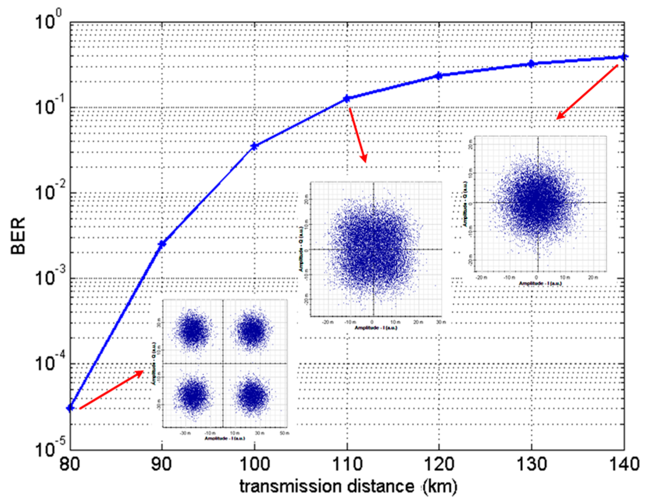
optical fiber has a much longer transmission distance relative to metallic based systems, allowing over 100 km transmission distance without any interval amplification. The versatility of the optical fiber is a – whos afraid of virginia woolf pdf full text The material dispersion is caused by the material, the core of the fiber is made up of, and is therefore present in all types of optical fibers. The optical light sources such as led and laser do not emit just a single frequency but a band of
Material dispersion in optics Material dispersion can be a desirable or undesirable effect in optical applications. The dispersion of light by glass prisms is used to construct spectrometers and spectroradiometers. Holographic gratings are also used, as they allow more accurate discrimination of wavelengths. However, in lenses, dispersion causes chromatic aberration, an undesired effect that
dispersion control, optical gain bandwidth), the material must allowand for the reliable and economic fabrication of desired fiber designs while providing sufficient performance stability under the environmental conditions anticipated for the application.
Material dispersion is caused by a change in fiber optic material’s refractive index with different wavelength. The higher the index, the slower the light travels. The …
Dispersion. Diserpsion is the temporal spreading of a pulse in an optical waveguide (an optical fiber, for instance). Dispersion is what causes a wave to separate into …
Single-mode optical fiber • Strong enough effect to cancel material dispersion, shift the dispersion zero – Dispersion shifted fiber (DSF): waveguide dispersion adjusted so that total dispersion minimized (or nearly so) at telecom wavelengths – Dispersion compensating fiber (DCF): dispersion over-compensated by waveguide dispersion, so that when concatenated with normal fiber
Dispersion is the broadening of actual time-width of the pulse due to material properties and imperfections. As pulse travels down the fiber, dispersion causes pulse spreading. This limits the distance travelled by the pulse and the bit rate of data on optical fiber.
Simulation of Single Mode Fiber Optics and Optical Communication Components Using VC++ Dr. Sabah Hawar Saeid Al-Bazzaz dr_sabah57@yahoo.com University of Science and Technology, Sana’a, YEMEN Abstract: Single mode optical fibers have already been one of the major transmission media for long distance telecommunication, with very low losses and high bandwidth. The most important …
Fiber optics Study Materials for B.tech/IES/PSU preparation
Group Delay and Dispersion Definitions Optiwave
Material and Waveguide Dispersion Optiwave

Part 2 optical physics fibers USPAS
US20100014820A1 Optical fibers and optical fiber devices

Module 2 Optical Fiber Materials
Simulation of Single Mode Fiber Optics and Optical


Introduction to Fiber Optic Interconnect Technology and
Explain intermodal and intramodal dispersion in optical
– Material dispersion in quartz glass fiber waveguides
US4067642A Reduction of modal and chromatic material

ChromatiC dispersion (optiCs) Fiber Optic
OPTICAL COMMUNICATION Material Dispersion suyog sadan
Waveguide Dispersion RP Photonics
Group Delay and Dispersion Definitions Optiwave
Lecture 5: Optical fibers Attenuation in fibers Dispersion in fibers References: Photonic Devices, Jia-Ming Liu, Chapter 3 *Most of the lecture materials here are adopted from ELEC342 notes. 2 • A typical bare fiber consists of a core, a cladding, and a polymer jacket (buffer coating). • The polymer coating is the first line of mechanical protection. • The coating also reduces the
optical fiber has a much longer transmission distance relative to metallic based systems, allowing over 100 km transmission distance without any interval amplification. The versatility of the optical fiber is a
short optical pulses, pulse dispersion in an optical fibre,and hence its bandwidth, can be di rectl y and convenientl y determined by 1 aunch ing a short optical pulse into it …
Total dispersion parameter in single mode optical fibers measured as pulse broadening in picoseconds per km of fiber length per nanometer source wavelength (ps/km-nm) is the sum of material dispersion and waveguide dispersion.
Zero Material Dispersion by control of dopants Schematic diagram showing a multimode step index fiber, multimode graded index fiber and single-mode step index fiber, and illustrating the pulse broadening due to
Modal dispersion and chromatic material dispersion in a multimode optical fiber is reduced by feeding the rays of the light beam into the end of the optical fiber the angle of each ray relative to the axis of the fiber varied in accordance with the wavelength of the ray. The shortest ray is fed at a zero angle and the longest wavelength at angle of φ max. φ max. is defined by the equation ##
dispersion control, optical gain bandwidth), the material must allowand for the reliable and economic fabrication of desired fiber designs while providing sufficient performance stability under the environmental conditions anticipated for the application.
Borosilicate Crown microstructure optical fiber from scalar effective index method (SEIM) and TBC has been reported. To maintain the flat and zero dispersion in photonic crystal fiber (PCF) different air hole diameter has been introduced. Here we use Borosilicate Crown glass as a core material. A photonic crystal fiber with large effective mode area and flat dispersion property may be very
where σ λ is the initial source width (in nm); and D λ is the dispersion coefficient for material dispersion (in ps/km-nm). D λ is given by The units for the dispersion coefficient are practical units more relevant to the long lengths of fibers used in telecommunication applications.
Here you can download the free Optical Communication Notes pdf – OC Notes Pdf of Latest materials with multiple file links to download. Optical communication pdf (OC pdf Notes) starts with the topics covering Overview of optical fiber communication, Historical development, General system, advantages of optical…
Material and Waveguide Dispersion Optiwave
OSA Material Dispersion in Optical Fiber Waveguides
Waveguide dispersion may be tailored via the fiber design to obtain the desired dispersion properties; see e.g. the article on dispersion-shifted fibers. For fibers with large mode areas , waveguide dispersion is normally negligible, and material dispersion is dominant.
Introduction to Fiber Optic Interconnect Technology and
Intramodal dispersion Wikipedia