Losses in optical fiber pdf
The notes gives a comprehensive approach to fundamentals of optical fibers and their propagation characteristics,a simplified approach.
26/06/2012 · Absorption losses in optical fibers Absorption of signal is a serious loss mechanism in an optical fiber. Absorption occurs in optical fibers due to the presence of imperfections in the atomic structure of the fiber material, due to some basic inherent intrinsic material properties and due to some extrinsic material properties.
Microbend loss fiber optic direction and amplitude sensors for underwater applications Ashish M. Vengsarkar, Kent A. Murphy, Tuan A. Tran, and Richard O. Claus
Module 4 : Signal Distortion on Optical Fibers – Attenuation Lecture : Signal Distortion on Optical Fibers – Attenuation Objectives In this lecture you will learn the following Signal distortion Condition for signal distortion-less transmission Special nature of Optical Signal Attenuation on Optical Fiber Material Loss Scattering Loss Micro-Bending Losses Radiation or Bending Loss What is
Generator Losses – Copper,Hysteresis, Eddy Current and Mechanical losses. Minor losses in bends lab report.docx . Major and Minor Losses in Pipes
Loss budget analysis is the calculation of a fiber optic cabling system’s estimated loss performance characteristics. This is sometimes confused with the communication system “power budget” which is a specification of the dynamic range of the electronics, the difference between the output power of the transmitter coupled into the fiber and the minimum received power required at the receiver
University of Technology 39 Laser and optoelectronics Dept Optical Fiber Communication Lab By lecturer Jassim K. Hmood Experiment No. 9 Bending Losses in Optical fiber
Calculating Fiber Optic Loss Budget Criteria & Calculation Factors Design of a fiber optic system is a balancing act. As with any system, you need to set criteria for
Optical Fiber Splice Loss Application Notes Author Madhan Thollabandi, Arvind Mishra, Sudipta Bhaumik Issued July 2013 Supercedes July 2006 Abstract To build a network with optical fibers, one may eventually join two fiber ends with a connector or fusion splicer. The amount of optical power lost at these connections is a concern for many system designers. This application note discusses the
In the optical communication systems that are in operation today, one uses laser diodes (LD) with λ 0 ≈1550 nm having a spectral width of about 2 nm. Thus, for a 1-km length of the fiber, the
Crucial aspect of fiber joints concerning Optical Losses associated with the connection 1. Fresnel Reflection Optical Loss encountered at the interfaces (Even when two fiber ends
Technical Information about Fibre optic attenuation and loss values.
Introduction to Optical Fibers dB Attenuation and

Bending Losses in Optical Fiber Optical Fiber Fiber
Loss Budget: The maximum amount of power that is allowed to be lost per optical link. Multimode: A type of fiber optic cable where the core diameter is much larger than the wavelength of light transmitted.
loss on single mode fiber optic. The tuned of the laser wavelength allows the measurement of the bending losses as function of the wavelength. IV. D
Abstract: Bending losses of power in a single mode step index optical fiber due to macro bending has been investigated for a wavelength of 1550nm. The effects of bending radius (4-15mm, with steps of 1mm), and wrapping turn (up to 40 turns) on loss have
This parameter reveals the maximum optical loss an OTDR can analyze from the backscattering level at the OTDR port down to a specific noise level. In other words, it is the maximum length of fiber that the longest pulse can reach. Therefore, the bigger the dynamic range (in dB), the longer the distance reached. Evidently, the maximum distance varies from one application to another since the
Issue 2 Page 1 of 9 Practical Fiber Optic Loss Measurement Uncertainty B.Robertson, N.Razbash, B.Crook, Kingfisher International P/L 11 th August 11, 2008
Absorption loss is caused by the presence of impurities such as traces of metal ions (e. and they follow a distribution law throughout the fiber. optical losses in the glass cause the optical power in a fiber to fall off exponentially with the length L of the fiber. whereas. amorphous structures.95 µm. Scattering Losses Despite the careful manufacturing techniques. light striking a Rayleigh
For silica fiber, the lowest losses of about 0,18 dB/km can be obtained in the region of 1550 nm. They are very close to the fundamental scattering limit. For longer wavelengths, silica attenuation is increasing. In order to obtain fiber with lower losses than silica waveguides, it is necessary to implement different materials with low intrinsic absorption in a more far infrared region.

The simultaneous availability of compact sources and of low-loss optical fibres led to a worldwide effort for developing optical fibre communication systems. The real research phase of fibre-optic communication systems started around 1975.
Absorption is a major cause of signal loss in an optical fiber. Absorption is defined as the portion of attenuation resulting from the conversion of optical power into another energy form, such as heat.
Bend Loss . 1. A form of increased Attenuation in a Fiber that results from bending a fiber around a restrictive curvature (a macrobend) or from minute distortions in the fiber (microbends). 2. A form of increased attenuation caused by allowing high order Modes to radiate from the walls of a fiber optic cable. There are 2 common types of bend losses. The first type results when the fiber optic
118 Y. M. GAO . ET AL. 2.2. Contrast Experiments on Different Polymer Coat Materials . In the experiments, we made two optical fiber preforms
losses by direct contacting of opto-electronic devices. Keywords: polymer optical fiber, power transmission, micro dispensing, component inherent communication
Bend losses are a frequently encountered problem in fiber optics: optical fibers exhibit additional propagation losses when they are bent. Typically, these losses rise very quickly once a certain critical bend radius is reached.
15dBm, optical loss for the fiber is calculated as: Input Output Optical Loss 0dBm – (-15dBm) =15dB In the power conversion table, 15dB for optical loss equals 96.8 percent of lost optical power. Therefore, only 3.2 percent of optical power remains when it travels through the fiber. Understand Insertion Loss In any fiber optic interconnection, some loss occurs. Insertion loss for a connector
signal loss at optical fiber spliced joints a project report submitted in partial fulfilment of the requirements for the award of the degree of

Analysis of Power Coupling and Losses at Splice Joints of Dissimilar Optical Fibers Power coupling, Losses, Splice joints, Single-mode fiber, Photonic crystal fiber . 1. Introduction . One of the bottlenecks in implementing an optical network is the well-known splice losses between transmission fibers and fiber-based devices, such as optical dispersion compensators, optical attenuators
Propagation loss in optical fibers Current loss is < 0.2dB/km for singlemode fiber working around 1550nm. Fiber optics telecommunication 1. Low loss optical fiber based on fused silica 2. Compact, low-cost diode lasers. Fiber optics telecommunication Predict the loss in optical fiber could be < 20dB/km Loss was ~1000dB/km at that time. Questions for thoughts •What are the techniques to
Bending Losses in Optical Fiber – Download as PDF File (.pdf), Text File (.txt) or read online.
The Importance of Minimizing Hydrogen Aging Losses and Alkali Impurities generating services the optical loss in fibers should not degrade with time. For some fibers, however, there is a significant risk that the optical loss could increase due to the chemical reactions between the atomic defects in fibers and the trace amounts of molecular hydrogen inevitably present in or around optical
Design and Simulation of a Low Loss Optical Fiber Coupler 475 a. through the fiber core cross section by butt joining the fibers or by using some
Multimode fiber is large enough in diameter to allow rays of light to reflect internally (bounce off the walls of the fiber). Interfaces with multimode optics typically use LEDs as light sources. However, LEDs are not coherent sources. They spray varying wavelengths of light into the multimode fiber
The Loss of Optical Fiber with Pure Quartz Core and
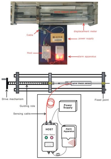
The optical fiber bending loss phenomena is used as a transduction effect in some types of intrinsic optical fiber sensors (temperature, displacement, strain…) [1,2,13-20]. The step-index optical fiber that we use is curved dur-ing its manufacturing at a high temperature. A geometri- cal modeling is used to describe the light propagation in the optical fiber and to determine the light power
Optical fiber tapers with a waist size larger than 1μm are commonplace in telecommunications and sensor applications. However the fabrication of low-loss optical fiber tapers with subwavelength diameters was previously thought to be impractical due to difficulties associated with control of the surface roughness and diameter uniformity. In
fiber cores placed in capillary tubes (a rod-in-tube process). Although the losses were very high as measured with HeNe laser light, the results suggested that better glasses and pro-
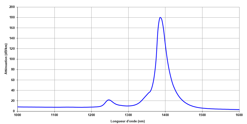
Figure 3.1: Optical fiber attenuation characteristics that bound the transmission window in GeO2-doped, low-loss, low-OH-content silica fiber. Of course, the precise frequency dependence (e.g. energy location of these absorption edges) will
Fiber Optics, Prof. R.K. Shevgaonkar, Dept. of Electrical Engineering, IIT Bombay Page 2 The distortion of optical signal in an optical fiber is a very important issue for analysis. This distortion to the optical signals may come from mainly two sources- dispersion and attenuation. Dispersion and attenuation may result due to a variety of factors such as the material properties, modal
In any fiber optic interconnection, some loss occurs. Insertion loss for a connector or splice is the difference in power that you see when you insert the device into the system. For example, take a length of fiber and measure the optical power through the fiber. Note the reading (P1). Now cut the fiber in half, terminate the fibers and connect them, and measure the power again. Note the
For example, to determine the light loss of an optical fiber in a cable, a light source is connected to one end of the fiber cable (input). The light output power of the source is known to be 0.1 mW. – optical fiber communication notes pdf • It is common to wrap optical fiber in communication systems OPTI 500 C, Spring 2011, Lecture 24, Bend Loss, Nonlinear Effects 1 Bend Loss in Optical Fibers
In telecommunications, return loss is the loss of power in the signal returned/reflected by a discontinuity in a transmission line or optical fiber. This discontinuity can be a mismatch with the terminating load or with a device inserted in the line. It is usually expressed as a ratio in
The optical net will operate properly, when we first select the proper optical fiber, apply the proper light transmitter that emits the light which is directed into the fiber, as well as the proper receiver that detects the light at the end of the fiber.
Loss & Continuity Testing with MPO/ MTP Connectors Deployments of fiber optic systems typically MPO/MTP connectors , which have Here we give an overview of how to tackle various issues related to testing the cabling for these
In order to improve the OSNR, optical fibers with low transmission loss and large effective area (Aeff) are in strong demand. This paper reports on a pure-silica-core fiber (PSCF) with the record-low loss of 0.149 dB/km, which is
berganza et al.: misalignment losses in step-index multicore plastic optical fibers 2183 a region between cores in the endface of the receiving fi ber, in- creasing the longitudinal separation
Brillouin Losses in Optical Fiber Cheng Feng, Stefan Preußler, and Thomas Schneider Abstract—In this paper, we propose a low-noise, bandwidth tunable microwave photonics filter (MPF) based on stimulated Brillouin scattering (SBS) losses. By suppressing the out-of-band signal with two broadened symmetric SBS losses, pass bandwidth can be tuned from 500 MHz to 10 GHz. Considering the …
The fibre loss equation in the link model spreadsheet predicts 0.34 dB/km at 1550 nm and 0.4 dB/km at 1300 nm, thus any attempt to use this equation for CWDM applications seems to be problematic.
Analysis of Power Coupling and Losses at Splice Joints of
SIGNAL LOSS AT OPTICAL FIBER SPLICED JOINTS

Bend Losses RP Photonics
Laser and optoelectronics Dept By lecturer Jassim K. Hmood
Losses in Optical Fiber.docx PDF Free Download
Understanding Fiber-Optic Cable Signal Loss Attenuation
Making the First Low-Loss Optical Fibers
Microbend loss fiber optic direction and amplitude sensors
– Power Transmission by Optical Fibers for Component
Attenuation in Fiber Optics Physics – Metropolia Confluence


Optical Losses Optical Fiber Attenuation
[artigo 2vers] Modeling of Bend Losses in Single-Mode
Bend Losses RP Photonics
Introduction to Optical Fibers dB Attenuation and
• It is common to wrap optical fiber in communication systems OPTI 500 C, Spring 2011, Lecture 24, Bend Loss, Nonlinear Effects 1 Bend Loss in Optical Fibers
In order to improve the OSNR, optical fibers with low transmission loss and large effective area (Aeff) are in strong demand. This paper reports on a pure-silica-core fiber (PSCF) with the record-low loss of 0.149 dB/km, which is
The fibre loss equation in the link model spreadsheet predicts 0.34 dB/km at 1550 nm and 0.4 dB/km at 1300 nm, thus any attempt to use this equation for CWDM applications seems to be problematic.
Bending Losses in Optical Fiber – Download as PDF File (.pdf), Text File (.txt) or read online.
Optical Fiber Splice Loss Application Notes Author Madhan Thollabandi, Arvind Mishra, Sudipta Bhaumik Issued July 2013 Supercedes July 2006 Abstract To build a network with optical fibers, one may eventually join two fiber ends with a connector or fusion splicer. The amount of optical power lost at these connections is a concern for many system designers. This application note discusses the
loss on single mode fiber optic. The tuned of the laser wavelength allows the measurement of the bending losses as function of the wavelength. IV. D